I recently found most of the architectural plans that were drafted in 1955 and 1956, by the local firm Hitchcock & Hitchcock. All images are photographs of the plans. Citation:Architectural Sketches and Blueprints, 1907-1987, Box 13, Folder Number 1, Hitchcock & Hitchcock (Firm) records, Collection Number 09921, American Heritage Center, University of Wyoming.
The area site plan: 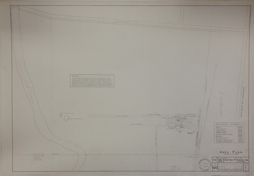
Items of note include: What is now Curtis Street is shown as a county road, and the original still bank on the west side of the building is still intact, as is the oil/water separator & water treatment plant. Pine Street dead ends exactly the same today as it did then; but Cedar Street isn’t included. The “Exist Power Line” is no longer present. The “Exist Gas Meter”, (lower right), today is a sealed gas line, and the “Exist 4″ C.I. water and Exist 6″ Sewer” still remain.
Detail of above image:
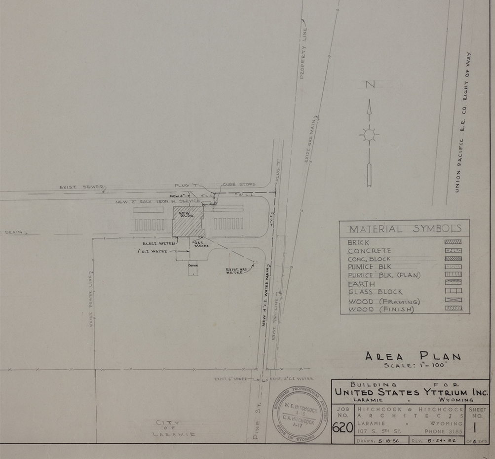 Note the original draft date of 18May56, with a revision date just over three months later.
 The exterior elevation sheet. The draft called for concrete blocks and glass blocks for the windows. The also indicated the use of stucco for the exterior “walls” that were originally furnace walls. Any exiting opening that wasn’t going to be utilized were ordered to have bricks used as filler.
 Layout of the first floor and uses for each area. The south factory floor was a storage area, the north area that was created between the refinery furnaces and the refinery machinery rooms was slated as a work room. Two of the machinery rooms became laboratories.
 The Longitudinal Section sheet indicates where both the elevator and a spiral staircase were to be installed.
 Detail of the Longitudinal Section Plate.
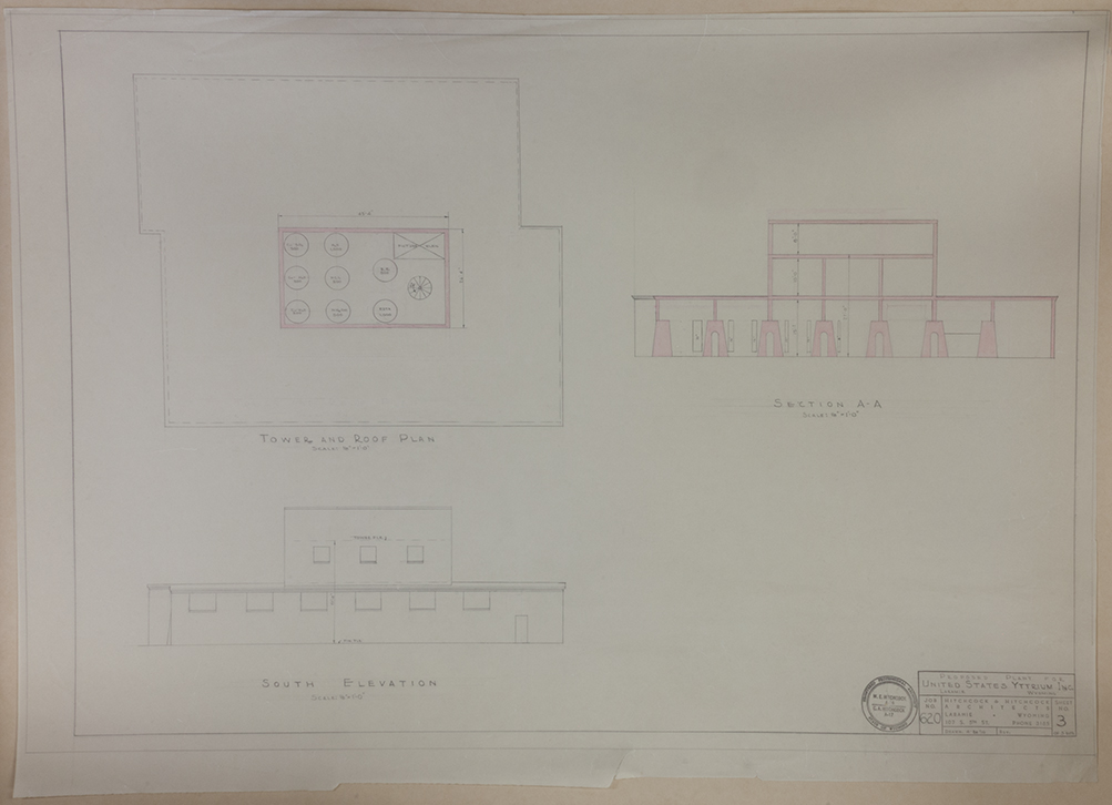 South exterior and tower roof plan. Note the windows for the third floor are not included.
 Detail of tower and roof plan.
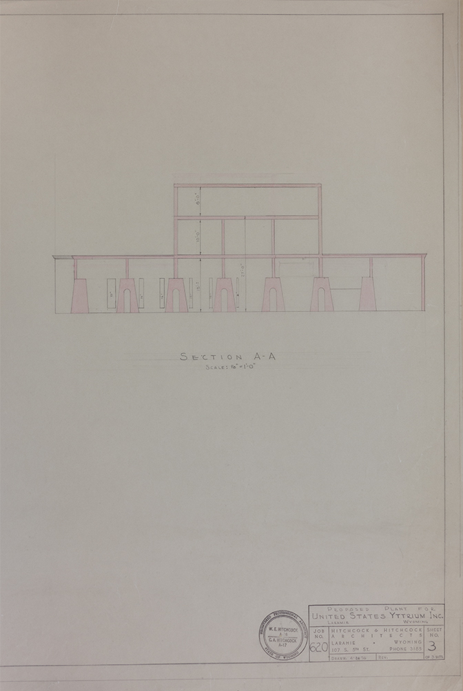 Detail of the furnaces being incorporated into the construction.
 Third floor plan, full plate.
 Third floor & Tower roof detail.
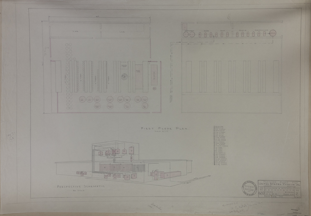 This plate indicates the placement and routing of various piping, storage tanks, and other machinery involved in yttrium processing.
 Detail of first floor, and an indication of the location of various items and the routing of piping for the chemicals and elements, (all items listed below).
 This has a list of all of the various elements and chemicals that were going to be used, mixed, or stored on site.
Here is a complete listing, (with additional information as needed):
1 – Deionizer (water purification)
2 – Degassifier (removing gas from liquids)
3 – H2O storage
4 – EDTA mixing
5 – NH4 storage
6 – NH4 mixing (Ammonium)
7 – HCl mixing (Hydrogen Chloride)
8 – HCl storage
9 – CuSO4 mixing (Copper Sulfate)
10 – Cu-H2O mixing (Copper Hydroxide)
11 – Cu-H2O mixing
12 – R.E. Storage (Rare Earth)
13 – NH4Cl Storage (Ammonium Chloride)
14 – Cu storage (Copper)
15 – Yttrium storage
16 – 27″ Tubes
17 – 16″ Tubes
18 – 10″ Tubes
19 – 6″ Tubes
20 – H2O purifying
21 – H2O storage
22 – NH4 storage
23 – R.E. storage
24 – Cu -H2O storage
25 – EDTA storage
26 – HCl storage
27 – Cu-H2o storage
28 – CuSO4 storage
The images shown on this page are low-resolution. Contact me for high-resolution copies.
-Doc

Leave a comment